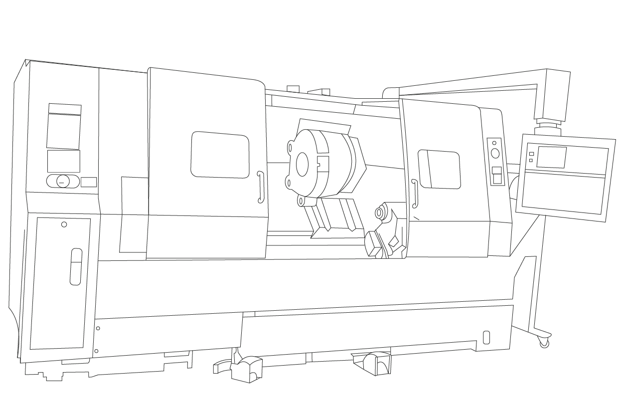
CNC (computer numerical machining) is the pinnacle of precision and efficiency in modern subtractive manufacturing. The indispensable role of a CNC lathe in producing cylindrical parts underscores their significance in the manufacturing industry.
CNC lathes are motorized machines equipped with a multi-tool post. A program that interprets G-code that controls the operations, enabling the machine operator to take a hands-off approach and ensuring highly repeatable production without human error. CNC lathes consist of several distinct components that define their identity and functionality.
This blog post will explore the main CNC lathe components and their functions.
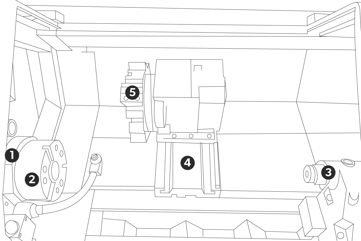
The components of a CNC lathe.
A Computer Numerical Control (CNC) lathe is a versatile machine tool that employs computer automation for machining operations. Key components include:

1. Headstock 2. Spindle & Chuck 3. Tailstock 4. Bed 5. Tool Turret
1. Headstock
The headstock, a crucial component of a CNC lathe, is a testament to the machine’s versatility. It houses the spindle, which holds and rotates the blank. The spindle motor allows for various speeds, settings, and drive mechanisms, making it suitable for a wide range of machining tasks.
The dimensions of the headstock determine the lathe’s “swing,” which refers to the maximum diameter of any pre-machined workpiece that can fit onto the lathe. While most tasks do not require large workpieces, having a lathe with a more excellent swing can be advantageous in certain situations.
2. Spindle & Chuck
The spindle is the rotating element of the headstock in a machining setup, securely holding the workpiece for the duration of the machining process. Its design accommodates various chuck types, including three-jaw and four-jaw chucks, which are essential for effectively gripping different shapes and sizes of materials. The choice of the chuck hinges on the machining requirements and the geometry of the material.
A key attribute of the spindle is its ability to adjust rotational speed. Allowing the operators to fine-tune the spindle’s performance based on the type of material and the cutting techniques employed. For instance, the more rigid the materials, the slower the speed to prevent tool wear. The softer the material, the higher the speed for increased efficiency. The adaptability in speed control improves the machining process’s precision and contributes to better tool life and overall production efficiency. By optimizing these parameters, machinists can achieve superior surface finishes and more accurate dimensions on the final product.
3. Tailstock
The tailstock, positioned opposite the headstock on a lathe, is a critical component for maintaining precision and stability during the machining process. It plays a key role in securing the workpiece, preventing deflection or vibration that could compromise the quality of the final product.
A key feature is the adjustability along the lathe bed, accommodating workpieces of different lengths. Longer or slender materials must ensure accuracy in machining operations.
Equipping the tailstock with a live center supports and rotates the workpiece or a drill chuck to attach drill bits and taps, allowing for various auxiliary operations.
Effective use of the tailstock is crucial for achieving high-quality results. It reduces the risk of workpiece deformation and enhances safety, significantly contributing to machining accuracy and efficiency.
4. Bed
The bed is a crucial component of the CNC lathe, acting as its foundational structure, which provides essential support for all of the other machine parts. Typically, it is made from durable materials like cast iron or steel. The bed’s design effectively absorbs vibrations, helping to maintain stability and rigidity during the machining process. This rigidity is vital for achieving high precision and accuracy in the finished products.
The bed has precision-machined ways—specially designed grooves that facilitate the smooth movement of the carriage and tailstock along the machine’s length. This careful machining ensures that any movement is controlled and accurate, minimizing errors during operation. As a result, the bed plays a pivotal role in ensuring that the CNC lathe operates efficiently, producing parts that meet stringent tolerances and quality standards.
5. Tool Turret
The tool turret is a critical component mounted on the carriage of a CNC machine, specifically designed to securely hold the various cutting tools in place during machining operations. It accommodates many tools, including turning, boring bars, and threading tools, each essential for different machining tasks. The design of the tool post facilitates quick and easy tool changes, allowing operators to swiftly switch between tools as needed, which is vital for maintaining high efficiency and productivity in CNC machining processes. This feature minimizes downtime and enhances the machine’s versatility, enabling it to handle diverse manufacturing needs. The robust construction of the tool turret ensures stability and precision during operation, contributing to the overall accuracy of the machining process.
Carriage
The carriage is an essential CNC (Computer Numerical Control) machine component. It enables the movement of the cutting tool across the workpiece. It consists of interconnected parts: the saddle, cross slide, and tool post.
The saddle provides stability and supports the cross slide, which moves horizontally to adjust the cutting tool’s position laterally. The cross slide is vital for setting the cut depth and achieving precise dimensions. Above it, the tool post mounts the cutting tool for easy replacement.
The carriage can move in horizontal and vertical planes, allowing for accurate positioning of the cutting tool relative to the workpiece. This dual-axis capability is crucial for complex machining tasks that demand tight tolerances.
A CNC system controls the carriage’s movement, interpreting programmed instructions to automate the machining process. It enhances precision and repeatability, significantly improving manufacturing efficiency.
CNC Control System
The CNC control system, serving as the central processing unit of the lathe, is the ‘brain’ that orchestrates the entire machining process. It is responsible for interpreting G-code programs, which are instructions that detail specific machining operations, including movements and tool actions. Operators can input various parameters through this system, such as spindle speed, which determines how fast the tool spins; feed rate, which controls the speed at which the tool moves along the material; and specific tool paths, which indicate the precise routes that the cutting tools will take during the machining process.
The designs of modern CNC control systems with user-friendly interfaces enhance usability. This allows the operators to monitor machine performance in real-time. These interfaces often include visual displays and intuitive controls that provide immediate feedback on parameters and machining status. Furthermore, many systems allow on-the-fly adjustments, enabling operators to modify settings during the machining process to optimize efficiency and precision. This combination of advanced technology and accessibility empowers machinists to achieve high accuracy and productivity in their work.
Coolant System
A coolant system is an essential component of a CNC lathe. It enhances machining efficiency and extends the cutting tool’s lifespan. The system consists of a reservoir, pump, and delivery channels, providing a steady coolant flow to the cutting area.
The coolant primarily reduces heat generated during machining, preventing thermal expansion and tool wear. It also removes chips and debris from the cutting zone, which is vital for optimal performance, as accumulated chips can hinder the process and affect the surface finish.
Coolant also improves cutting speeds and feeds, leading to a better surface finish while minimizing defects. Overall, a well-designed coolant system maximizes efficiency, improves tool life, and achieves high-quality machining results.
Conclusion
Understanding the various parts of a CNC lathe is essential for anyone involved in machining. Each component ensures precision and efficiency in producing high-quality cylindrical parts. As technology advances, CNC lathes continue to evolve, incorporating new features and capabilities that enhance their performance in the manufacturing industry. Whether you’re a seasoned machinist or just starting, familiarizing yourself with these components will improve your machining skills and knowledge.
FAQs
A CNC lathe is a computer-controlled machine tool that precisely shapes and cuts cylindrical parts.
A CNC (Computer Numerical Control) lathe is a highly automated machine tool that uses computer-controlled motors to precisely shape and cut materials into desired parts. It offers unparalleled accuracy and efficiency in manufacturing.
Mastering CNC lathe programming involves understanding G-code, setting tool offsets, and optimizing feed rates and speeds for efficient part production. Our experts can guide you through the process.
Setting up a CNC lathe involves selecting a proper chuck, tool selection, and programming to ensure precise, efficient machining. Our experts can guide you through the process for optimal performance.


