Fillets and Chamfers: Which is the Best Choice?

Table of Contents

Fillets and Chamfers: Which is the Best Choice?

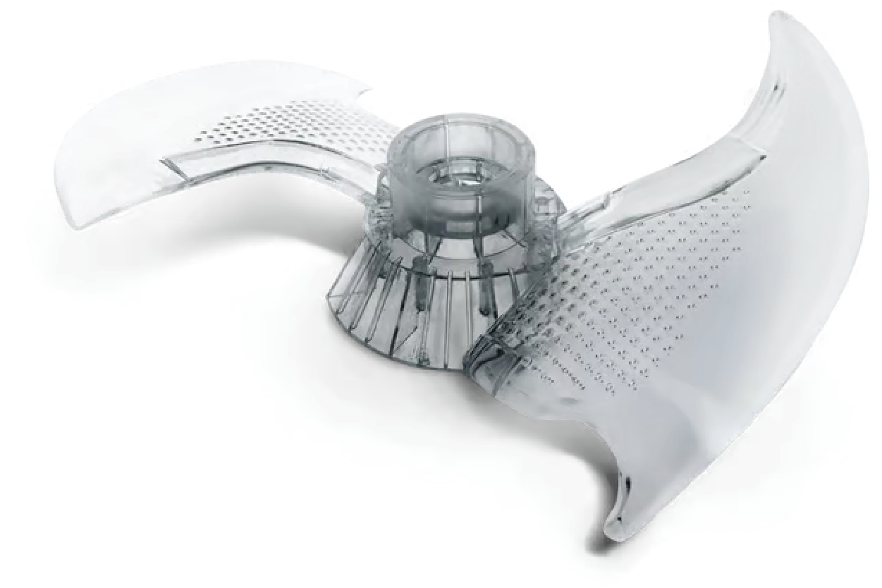
Design features fillets and chamfer for CNC machined parts.

Choosing between a fillet and a chamfer in manufacturing and engineering can significantly impact the final product. Both features serve essential purposes, but determining the best option for your application requires careful consideration. In this blog post, we’ll explore the key differences between fillets and chamfers, their advantages and disadvantages, and a guide to help you make an informed decision for your next project.

What are the differences between fillets and chamfers?

Fillets and chamfers are two standard design features used in manufacturing and engineering. The critical difference is that a fillet is a rounded internal or external corner, while a chamfer is a beveled edge. Fillets help reduce stress concentrations and improve a part’s appearance, while chamfers facilitate assembly and ease the flow of materials.

What is a fillet?

A fillet is a smooth, rounded curve that transitions between two intersecting surfaces, either on the interior or exterior of a component. This elegant design feature is widely utilized in manufacturing and engineering, as it not only improves the structural integrity of a part by reducing stress concentration points but also enhances its visual appeal. Fillets simplify fabrication, making machine and assembly components more accessible while promoting better flow in fluid applications. Overall, the incorporation of fillets contributes to the durability and functionality of engineered products.

What is a chamfer?

A chamfer is an edge treatment characterized by a sloping or beveled cut at the corner of a part, which serves various purposes in both functionality and aesthetics. Its primary role is to create a smoother transition between two surfaces, minimizing sharp edges that could cause injury or wear. Chamfers are widely utilized in manufacturing and engineering applications, as they help reduce stress concentrations, improve the fit of assembled parts, and facilitate easier machining processes. Additionally, chamfers enhance the visual appeal of components, providing a more finished and professional look. They can be found in various materials and designs, making them a versatile feature in product development.

Chamfer vs Fillet

Advantages and disadvantages of fillets and chamfers?

When it comes to part design, including fillets and chamfers can significantly impact your components’ overall functionality and manufacturability. In this section, we’ll explore these design features’ key advantages and disadvantages to help you make informed decisions for your next project.

Advantages of Fillets

Improved stress distribution: Fillets help to reduce stress concentrations at sharp corners, enhancing the part’s structural integrity and fatigue life.

Enhanced aesthetics: Smooth, rounded edges created by fillets can provide a more visually appealing and professional-looking finish to your parts.

Easier manufacturing: Fillets can simplify the manufacturing process, particularly for processes like CNC machining and injection molding, by reducing the risk of tool breakage and improving part ejection.

Advantages of Chamfers

Simplified assembly: Chamfered edges can facilitate the alignment and mating of parts during assembly, making the process smoother and more efficient.

Improved deburring: Chamfers can help to remove sharp edges and burrs, reducing the risk of injury during handling and assembly.

Enhanced part functionality: Chamfers can improve the flow of fluids or gases around the part, enhancing its performance in specific applications.

Disadvantages of Fillets and Chamfers

Increased material usage: Incorporating fillets and chamfers can slightly increase the overall material required for the part, which may impact the cost.

Potential for interference: Depending on the part’s design and the assembly requirements, fillets and chamfers may require careful consideration to avoid interference with other components.

Complexity in manufacturing: Fillets and chamfers can simplify specific manufacturing processes, but they can also add complexity, particularly for intricate or tight-tolerance parts.

When designing your parts, it’s essential to carefully evaluate the trade-offs between the advantages and disadvantages of fillets and chamfers. You can optimize your part design by striking the right balance for improved performance, manufacturability, and overall product quality.

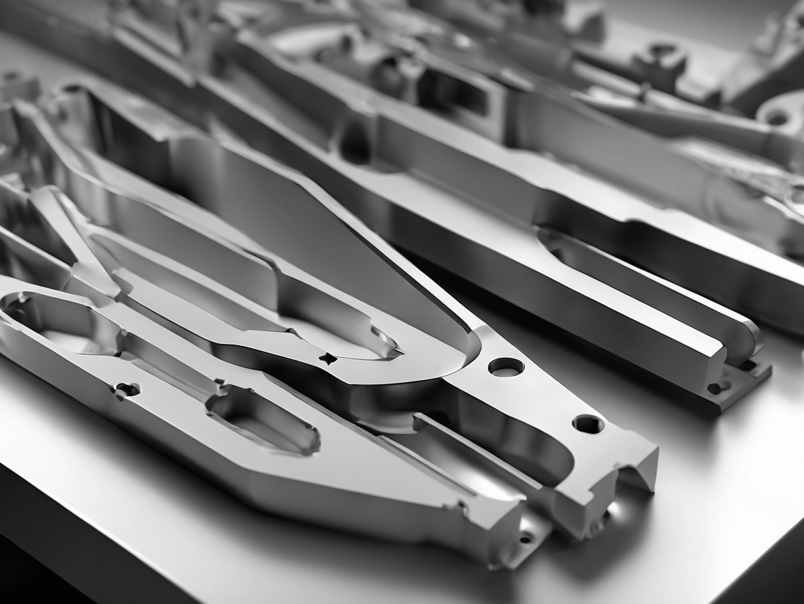
Gears with bevels and fillets.

How to decide whether your project needs one or the other.

Additive Manufacturing

Choosing between a fillet and a chamfer is a crucial design decision when preparing a 3D model for printing. Each feature serves distinct purposes and can significantly affect the final part differently.

To begin with, fillets are rounded corners that help strengthen and distribute stress throughout a part. Consequently, they are instrumental in preventing cracking or breaking, especially in high-stress areas. On the other hand, chamfers feature angled edges that enhance the part’s aesthetics, facilitate assembly, and eliminate sharp edges.

When designing for additive manufacturing, it is advisable to consider using fillets to reinforce critical areas and chamfers to improve your part’s appearance and functionality. Consulting with an experienced digital manufacturing partner can provide valuable guidance on utilizing these features for your project needs.

CNC Machining

Choosing between a fillet and a chamfer for your CNC machining project can significantly impact the final product. Both features serve different purposes and offer unique advantages. Therefore, it is essential to understand when to use each.

A fillet is a rounded internal or external corner formed by blending two surfaces. Fillets help reduce stress concentrations and improve the part’s appearance while facilitating easier handling. Consequently, fillets, such as consumer products or medical devices, are standard in applications where smooth transitions and aesthetics are critical.

On the other hand, a chamfer is a beveled edge created by removing a portion of material at an angle. Chamfers serve multiple purposes: ease tool entry, prevent sharp edges, and improve part assembly. As a result, they are particularly beneficial in applications where part fit and function are critical, such as in mechanical assemblies or structural components.

When deciding between a fillet and a chamfer, it is vital to consider your project’s specific requirements. These include the part’s intended use, the manufacturing process, and the desired appearance. By thoroughly understanding the differences and selecting the appropriate feature, you can ultimately optimize the performance and quality of your CNC machined parts.

Are you ready to start your project?

FAQs

What is a fillet in manufacturing?

A fillet is a smooth, rounded transition between two surfaces in manufacturing, improving strength and reducing stress concentrations.

What is a chamfer in manufacturing?

A chamfer is a beveled edge or corner in manufacturing, used to ease the transition between two surfaces, improve aesthetics, and prevent sharp edges that could cause injury or damage.


The content on this blog post is for informational purposes only. Prototek does not make any declaration or guarantee, whether expressed or implied, regarding the information’s accuracy, completeness, or validity. Any performance parameters, geometric tolerances, specific design features, quality and types of materials, or processes should not be assumed to represent what will be delivered by third-party suppliers or manufacturers through our network. It’s crucial to note that buyers seeking quotes for parts are responsible for defining the specific requirements for their project.

Standard Drill Bit Sizes

Drill Size

Imperial

Metric

#107

0.0019 in

0.0483 mm

0.05 mm

0.0020 in

0.0500 mm

#106

0.0023 in

0.0584 mm

#105

0.0027 in

0.0686 mm

#104

0.0031 in

0.0787 mm

#103

0.0035 in

0.0889 mm

#102

0.0039 in

0.0991 mm

0.1 mm

0.0039 in

0.1000 mm

#101

0.0043 in

0.1092 mm

#100

0.0047 in

0.1194 mm

#99

0.0051 in

0.1295 mm

#98

0.0055 in

0.1397 mm

#97

0.0059 in

0.1499 mm

#96

0.0063 in

0.1600 mm

#95

0.0067 in

0.1702 mm

#94

0.0071 in

0.1803 mm

#93

0.0075 in

0.1905 mm

0.2 mm

0.0079 in

0.2000 mm

#92

0.0079 in

0.2007 mm

#91

0.0083 in

0.2108 mm

#90

0.0087 in

0.2210 mm

#89

0.0091 in

0.2311 mm

#88

0.0095 in

0.2413 mm

#87

0.0100 in

0.2540 mm

#86

0.0105 in

0.2667 mm

#85

0.0110 in

0.2794 mm

#84

0.0115 in

0.2921 mm

0.3 mm

0.0118 in

0.3000 mm

#83

0.0120 in

0.3048 mm

#82

0.0125 in

0.3175 mm

#81

0.0130 in

0.3302 mm

#80

0.0135 in

0.3429 mm

#79

0.0145 in

0.3680 mm

1/64 in

0.0156 in

0.3969 mm

0.4 mm

0.0158 in

0.4000 mm

#78

0.0160 in

0.4064 mm

#77

0.0180 in

0.4572 mm

0.5 mm

0.0197 in

0.5000 mm

#76

0.0200 in

0.5080 mm

#75

0.0210 in

0.5334 mm

#74

0.0225 in

0.5715 mm

0.6 mm

0.0236 in

0.6000 mm

#73

0.0240 in

0.6069 mm

#72

0.0250 in

0.6350 mm

#71

0.0260 in

0.6604 mm

0.7 mm

0.0276 in

0.7000 mm

#70

0.0280 in

0.7112 mm

#69

0.0292 in

0.7417 mm

#68

0.0310 in

0.7874 mm

1/32 in

0.0313 in

0.7938 mm

0.8 mm

0.0315 in

0.8000 mm

#67

0.0320 in

0.8128 mm

#66

0.0330 in

0.8382 mm

#65

0.0350 in

0.8890 mm

0.9 mm

0.0354 in

0.9000 mm

#64

0.0360 in

0.9144 mm

#63

0.0370 in

0.9398 mm

#62

0.0380 in

0.9652 mm

#61

0.0390 in

0.9906 mm

1 mm

0.0394 in

1.0000 mm

#60

0.0400 in

1.0160 mm

#59

0.0410 in

1.0414 mm

#58

0.0420 in

1.0668 mm

#57

0.0430 in

1.0922 mm

1.1 mm

0.0433 in

1.1000 mm

#56

0.0465 in

1.1811 mm

3/64 in

0.0469 in

1.1906 mm

1.2 mm

0.0472 in

1.2000 mm

1.3 mm

0.0512 in

1.3000 mm

#55

0.0520 in

1.3208 mm

#54

0.0550 in

1.3970 mm

1.4 mm

0.0551 in

1.4000 mm

1.5 mm

0.0591 in

1.5000 mm

#53

0.0595 in

1.5113 mm

1/16 in

0.0625 in

1.5875 mm

1.6 mm

0.0630 in

1.6000 mm

#52

0.0635 in

1.6129 mm

1.7 mm

0.0669 in

1.7000 mm

#51

0.0670 in

1.7018 mm

#50

0.0700 in

1.7780 mm

1.8 mm

0.0709 in

1.8000 mm

#49

0.0730 in

1.8542 mm

1.9 mm

0.0748 in

1.9000 mm

#48

0.0760 in

1.9304 mm

5/64 in

0.0781 in

1.9844 mm

#47

0.0785 in

1.9939 mm

2 mm

0.0787 in

2.0000 mm

#46

0.0810 in

2.0574 mm

#45

0.0820 in

2.0828 mm

2.1 mm

0.0827 in

2.1000 mm

#44

0.0860 in

2.1844 mm

2.2 mm

0.0866 in

2.2000 mm

#43

0.0890 in

2.2606 mm

2.3 mm

0.0906 in

2.3000 mm

#42

0.0935 in

2.3749 mm

3/32 in

0.0938 in

2.3813 mm

2.4 mm

0.0945 in

2.4000 mm

#41

0.0960 in

2.4384 mm

#40

0.0980 in

2.4892 mm

2.5 mm

0.0984 in

2.5000 mm

#39

0.0995 in

2.5273 mm

#38

0.1015 in

2.5781 mm

2.6 mm

0.1024 in

2.6000 mm

#37

0.1040 in

2.6416 mm

2.7 mm

0.1063 in

2.7000 mm

#36

0.1065 in

2.7051 mm

7/64 in

0.1094 in

2.7781 mm

#35

0.1100 in

2.7940 mm

2.8 mm

0.1102 in

2.8000 mm

#34

0.1110 in

2.8194 mm

#33

0.1130 in

2.8702 mm

2.9 mm

0.1142 in

2.9000 mm

#32 

0.1160 in

2.9464 mm

3 mm

0.1181 in

3.0000 mm

3.1 mm

0.1221 in

3.1000 mm

1/8 in

0.1250 in

3.1750 mm

3.2 mm

0.1260 in

3.2000 mm

#30

0.1285 in

3.2639 mm

3.3 mm

0.1299 in

3.3000 mm

3.4 mm

0.1339 in

3.4000 mm

#29

0.1360 in

3.4544 mm

9/64 in

0.1406 in

3.5719 mm

5/32 in

0.1563 in

3.9688 mm

11/64 in

0.1719 in

4.3656 mm

3/16 in

0.1875 in

4.7625 mm

13/64 in

0.2031 in

5.1594 mm

7/32 in

0.2188 in

5.5563 mm

15/64 in

0.2344 in

5.9531 mm

1/4 in

0.2500 in

6.3500 mm

17/64 in

0.2656 in

6.7469 mm

9/32 in

0.2813 in

7.1438 mm

19/64 in

0.2969 in

7.5406 mm

5/16 in

0.3125 in

7.9375 mm

21/64 in

0.3281 in

8.3344 mm

11/32 in

0.3438 in

8.7313 mm

23/64 in

0.3594 in

9.1281 mm

3/8 in

0.3750 in

9.5250 mm

25/64 in

0.3906 in

9.9219 mm

13/32 in

0.4063 in

10.3188 mm

27/64 in

0.4219 in

10.7156 mm

7/16 in

0.4375 in

11.1125 mm

29/64 in

0.4531 in

11.5094 mm

15/32 in

0.4688 in

11.9063 mm

31/64 in

0.4844 in

12.3031 mm

1/2 in

0.5 in

12.700 mm

33/64 in

0.5156 in

13.0969 mm

17/32 in

0.5313 in

13.4938 mm

35/64 in

0.5469 in

13.8906 mm

9/16 in

0.5625 in

14.2875 mm

37/64 in

0.5781 in

14.6844 mm

19/32 in

0.5938 in

15.0813 mm

39/64 in

0.6094 in

15.4781 mm

5/8 in

0.6250 in

15.8750 mm

41/64 in

0.6406 in

16.2719 mm

43/64 in

0.6719 in

17.0656 mm

11/16 in

0.6875 in

17.4625 mm

45/64 in

0.7031 in

17.8594 mm

23/32 in

0.7188 in

18.2563 mm

47/64 in

0.7344 in

18.6531 mm

3/4 in

0.7500 in

19.0500 mm

49/64 in

0.7656 in

19.4469 mm

25/32 in

0.7813 in

19.8438 mm

51/64 in

0.7969 in

20.2406 mm

13/16 in

0.8125 in

20.6375 mm

53/64 in

0.8281 in

21.0344 mm

27/32 in

0.8438 in

21.4313 mm

55/64 in

0.8594 in

21.8281 mm

7/8 in

0.8750 in

22.2250 mm

57/64 in

0.8906 in

22.6219 mm

29/32 in

0.9063 in

23.0188 mm

21/23 in

0.9130 in

23.1913 mm

59/64 in

0.9219 in

23.4156 mm

15/16 in

0.9375 in

23.8125 mm

61/64 in

0.9531 in

24.2094 mm

31/32 in

0.9688 in

24.6063 mm

63/64 in

0.9844 in

25.0031 mm

1 in

1.0000 in

25.4000 mm

1 1/64 in

1.0156 in

25.7969 mm

1 1/32 in

1.0313 in

26.1938 mm

1 3/64 in

1.0469 in

26.5906 mm

1 1/16 in

1.0625 in

26.9875 mm

1 5/64 in

1.0781 in

27.3844 mm

1 3/32 in

1.0938 in

27.7813 mm

1 7/64 in

1.1094 in

28.1781 mm

1 1/8 in

1.1250 in

28.5750 mm

1 9/64 in

1.1406 in

28.9719 mm

1 5/32 in

1.1563 in

29.3688 mm

1 11/64 in

1.1719 in

29.7656 mm

1 3/16 in

1.1875 in

30.1625 mm

1 13/64 in

1.2031 in

30.5594 mm

1 7/32 in

1.2188 in

30.9563 mm

1 15/64 in

1.2344 in

31.3531 mm

1 1/4 in

1.2500 in

31.7500 mm

1 17/64 in

1.2656 in

32.1469 mm

1 9/32 in

1.2813 in

32.5438 mm

1 19/64 in

1.2969 in

32.9406 mm

1 5/16 in

1.3125 in

33.3375 mm

1 21/64 in

1.3281 in

33.7344 mm

1 11/32 in

1.3438 in

34.1313 mm

1 23/64 in

1.3594 in

34.5281 mm

1 3/8 in

1.3750 in

34.9250 mm

1 25/64 in

1.3906 in

35.3219 mm

1 13/32 in

1.4063 in

35.7188 mm

1 27/64 in

1.4219 in

36.1156 mm

1 7/16 in

1.4375 in

36.5125 mm

1 29/64 in

1.4531 in

36.9094 mm

1 15/32 in

1.4688 in

37.3063 mm

1 31/64 in

1.4844 in

37.7031 mm

1 1/2 in

1.5000 in

38.1000 mm