
In design, especially mechanical design, two or more components are assembled, fit, or slip over each other. Tolerances define the acceptable range of variation. At the same time, the fit describes how two or more parts will come together, for example, a shaft and a hole. The right combination of tolerances and fit will determine whether components assemble easily, function reliably, and are cost-effective.
In this blog post, we will take a look at the fundamentals, types, and how to read/use fit charts. By the end, you’ll be able to determine what fits your project needs. If you need further assistance, please get in touch with our team, and we will help.
What are the fundamentals of tolerances and fits?
What is a tolerance? A tolerance is the permissible variation in a dimension. It is the difference between the maximum and minimum limits.
What is a fit? To function, engineered products need to slip or press against each other. A fit is the relationship between the mating parts’ sizes. The tolerances determine them.
Why are tolerances and fit critical for mechanical designs?
- They guarantee correct assembly and function. Even in mass production.
- They can determine the manufacturing costs. A tighter tolerance means higher cost, but two loose tolerances can lead to poor performance.
- They enable interchangeability and quality control.
What are the different types of fits?
An overview of different types of fits:
- Clearance Fit: Always leaves a gap for easy assembly.
- Interference Fit: Always overlap so they require force or thermal assembly.
- Transition Fit: May be clearance or interference. These strike a balance between location accuracy and ease of assembly.
Clearance Fits
Definition: Clearance fits are fits where the shaft is always smaller than the hole, thus ensuring a gap or clearance under all tolerance conditions.
Characteristics:
- Guaranteed clearance, meaning there is no risk of binding.
- Easy assembly and disassembly, even by hand.
- Allows for movement, for example, rotations, sliding, or linear movement.
Classes and Typical Ranges (25 mm example):
| Fit Type | Example Fit | Minimum Clearance (mm) | Maximum Clearance (mm) | Typical Applications |
|---|---|---|---|---|
|
Loose Running |
H11/c11 |
0.11 |
0.37 |
Conveyor rollers and agricultural machinery. |
|
Free Running |
H9/d9 |
0.065 |
0.169 |
Low-precision bearings. |
|
Close Running |
H8/f7 |
0.020 |
0.074 |
Electric motor shafts. |
|
Sliding |
H7/g6 |
0.007 |
0.041 |
Machine tool slides. |
|
Locational Clearance |
H7/h6 |
0.000 |
0.034 |
Dowel pins and alignment holes. |
Advantages:
- Fast, tool-free assembly.
- Accommodates thermal expansion.
- Reduces risk of damage.
Disadvantages:
- Potential for play, vibration, or misalignment.
- Not suitable for high-precision location.
Interference Fits
Definition: A fit where the shaft is always larger than the hole, creating a press or friction fit that requires force or thermal methods for assembly.
Characteristics:
- Self-locking for high friction and no play.
- Permanent or semi-permanent assembly.
- No extra fasteners necessary.
Classes and Typical Ranges:
| Shaft Diameter | Typical Interference (mm) | Example Fit (ISO) | Application Example |
|---|---|---|---|
|
1-10 mm |
0.01-0.05 |
H7p6, H7/s6 |
Bearings, gears, and bushings. |
|
10-50 mm |
0.02-0.08 |
H7/p6, H7/s6 |
Flywheels and pulleys. |
|
50-100 mm |
0.05-0.15 |
H7/u6 |
Railroad wheels and couplings. |
Assembly Methods:
- Mechanical press, such as a hydraulic or arbor.
- The thermal method, such as heating the hub or cooling the shaft. For example, shrink fitting.
- Lubrication, which reduces assembly force.
Advantages:
- High strength and permanent joints.
- No additional fasteners.
- Reduces vibration and noise.
Disadvantages:
- Difficult or destructive disassembly.
- Requires precise machining and stress analysis.
- Risk of cracking if the interference is excessive.
Transition Fits
Definition: Transition fits may result in either a slight clearance or a slight interference. It depends on the actual part sizes within the tolerance bands.
Characteristics:
- Intermediate fits ballence between the clearance and interference.
- Probabilistic outcomes mean the actual fit depends on the manufacturing variation.
- Accurate location with a moderate assembly force.
Classes and Typical Ranges (50 mm example):
| Fit Class | Hole Tolerance | Shaft Tolerance | Typical Assembly | Application Example |
|---|---|---|---|---|
|
H7/k6 |
H7 |
k6 |
Light Tapping |
Gears, pulleys, and clutches. |
|
H7/n6 |
H7 |
n6 |
Moderate Pressing |
Motor armatures and collars. |
Advantages:
- Good balance of precision and ease of assembly.
- Reduces the risk of bearing creep or misalignment.
Disadvantages:
- Uncertainty in the final fit, either clearance or interference.
- Sensitive to manufacturing tolerances.
How to Read and Use Fit Charts
What are fit charts? These are also called tolerance charts. They are standardized tables that specify the permissible hole and shaft sizes to achieve a desired fit. They use codes, such as H7/g6 ISO or RC3 ANSI. Geometric Dimensioning and Tolerancing (GD&T) is the standardized language for specifying tolerances and assuring that parts meet functional requirements.
How to use:
- Select the fit type. The fit type depends on the application’s needs, such as clearance, interference, and transition requirements.
- Find the nominal size—for example, a 25 mm shaft.
- Look up the tolerance grades. The first number, H7, stands for the hole, and the second number, g6, is the shaft.
- Apply the upper and lower limits. Include these in your drawings.
Tip: Always refer to ISO 286 or ANSI/ASME B4.1 for official tables and recommended fits.
Examples and Applications of Tolerances and Fits
- Clearance Fit: An electric motor shaft in a bearing. The clearance fit allows free rotation and easy assembly.
- Interference Fit: Gear pressed onto a shaft. The interference fit ensures there is no slippage under load.
- Transition Fit: A pulley mounted on a keyed shaft. A transition fit allows for a precise location, but can be removed with moderate force.
How to choose which fit is suitable for a project?
There are a lot of questions you may need to ask yourself to determine what kind of fit will be the best option for your project, including some of the following:
Application and Functionality
- How do the components in the assembly interact?
- Do they require free rotation? (Clearance)
- Or do they require a tight, fixed connection? (Interference)
- Or do they have a precise location with minimal movement? (Transition)
Load and Stress Requirements
- Will the joint be exposed to forces or torques during its operations?
- Clearance fits are suitable for applications that have minimal loading requirements.
- Interference fits are ideal for transmitting high loads and torques.
- Transition fits provide an accurate location with some load-carrying capabilities.
Material Considerations
- Material choice plays an important role.
- Thermal expansion rates can alter a material, and therefore, the components fit significantly.
- The strength and ductility of a material can cause issues with excessive interference, leading to stresses and part failure.
Manufacturing Processes and Technologies
- A manufacturing process’s achievable tolerance can affect fit options.
- CNC machining has tighter tolerances than, say, casting or injection molding.
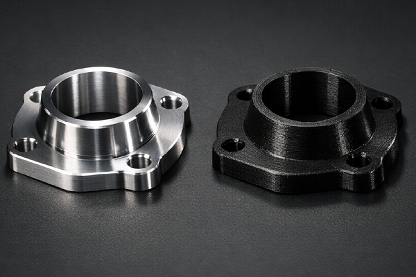
- 3D-printing components that require fits must account for material shrinkage, machine tolerances, build orientation, post-processing, and layer width.
Cost and Time Constraints
- One of the biggest choices is performance requirements, budget constraints, and timelines.
- Tighter tolerances require precision and can be more costly.
- Manufacturing processes, technologies, and post-processing may require longer timelines.
- Are you ready to make your manufacturing project a reality, or do you have questions?
FAQs
What are fits?
Fits refer to the relationship between two or more parts that work together, including how well they align, how tightly they fit, and how they interact with each other. A good fit is essential for the proper functioning and performance of a product or assembly.
What types of fits are there?
There are three main types of fits:
- Clearance Fit
- Interference Fit
- Transition Fit.
How do tolerances affect fits?
Tolerances specify the allowable variation in a part’s dimensions. Tight tolerances result in a precise fit, while looser tolerances yield a more flexible fit. The right tolerance balance is crucial for the intended function and assembly of the parts.
What are the common standards for fits and tolerances?
Common standards for fits and tolerances include:
- ANSI/ASME B4.1: Geometric Dimensioning and Tolerancing
- ISO 286-1: ISO System of Limits and Fits
- ISO 2768: General Tolerances
How to calculate the required tolerance for a specific fit?
To calculate the required tolerance for a specific fit:
- Type of fit for example, clearance, interference, or transition.
- Functional requirements, such as load, wear, thermal expansion.
- Manufacturing capabilities and limitations.
- Assembly and disassembly considerations.
Use engineering standards to determine the appropriate tolerance range for the desired fit.