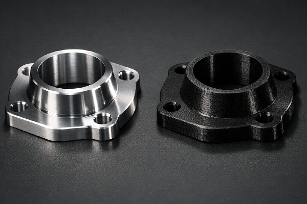

Stereolithography (SLA) is one of the most popular resin-based 3D printing technologies, due to its ability to produce high-precision, smooth surface finishes and complex geometries. Whether you’re a product designer, engineer, or hobbyist, understanding the nuances of designing for SLA can be the difference between a successful print and an obnoxious failure.
In this post, we’ll explore design tips for stereolithography to optimize your projects and achieve the best results.
Understand the SLA Process
Before diving into design tips, it’s crucial to understand how SLA works. SLA printers use a UV laser to cure liquid resin layer by layer, selectively. As each layer is completed, the tray lowers in the vat of resin, meaning the object is built from the bottom up. The process allows for high feature resolution but also comes with unique considerations regarding supports, orientation, and material properties.
Key Design Tips for Stereolithography
1. Wall Thickness
- Minimum Wall Thickness: For most standard resins, a minimum recommended wall thickness of 0.02 in for supported walls and 0.04 in for unsupported walls.
- Uniformity: Maintaining consistent wall thickness throughout the project reduces stress concentrations.
Why is this important?
Too-thin walls can lead to fragility, while too-thick walls can result in material waste and potential defects, such as warping.
In addition to stress concentrations, nonuniform walls tend to cool at different rates, leading to cracking, warping, and other defects.
Unsupported walls need to err on the thicker side, so if these are part of your project, all walls should be slightly thicker. Introducing fillets at the bases will also increase their strength. We’ll talk about these later on.
2. Supports and Overhangs
- Supports & Overhangs: Base support otherwise 45°. Supports are necessary under overhangs and bridges, as well as other features that may deform without support during the printing process.
Why is this important?
Designing your project to minimize overhang features is ideal; however, if they’re needed strategically, plan where they are. Doing this can reduce the number of supports required and improve the overall appearance of the 3D printed part.
After the SLA machine finishes the part, our technicians will remove the supports. Depending on the finishing requirements, sanding may be necessary to smooth the area where the supports attach to the part.
4. Orientation Matters
- Optimize Print Orientation: This will minimize the need for supports and make the surfaces more aesthetically pleasing.
- Layer Lines: The orientation will also affect the visibility of layer lines on the finished component.
Why is this important?
For the reasons above! Our engineers can help determine the best orientation of your components and ensure this is optimized. Additionally, consider the finishing and post-processing levels based on your project’s requirements.
5. Holes and Cavities
- Holes and Openings: Minimum hole size should be 0.02 in.
- Drainage Holes: When creating hollow components, ensure that you include drainage holes to allow the uncured resin to escape.
Why is this important?
If the holes are too small, they can close due to the resin overcuring, making them difficult to clean and maintain. If the holes are necessary for the design’s functionality, ensure they are larger than the minimum required size.
Trapped resin is not only that; it can also lead to defects or a sticky finish, and will not cure correctly if it needs to.
6. Reducing Warping and Stress
- Filleting: Adding these elements to sharp corners can alleviate stress concentrations and warping.
- Flat Portions: Large flat surfaces are prone to warping and can experience suction forces during the printing process.
Why is this important?
Mitigating stress concentrations with fillets can reduce the possibility of cracking and increase the durability.
Adding a slight curve to large flat areas or incorporating features can minimize warping and suctioning.
7. Post-Processing and Additional Considerations
- Assembly: Allow adequate clearance between parts when required, and consider incorporating chamfers and other design elements to facilitate easier assembly.
- Connecting and Moving Parts: Our recommended minimum clearance is 0.03 in for stereolithography components.
- Finishing Levels: We offer a variety of finishing levels for SLA components, which can be easily sanded, painted, and clearcoated.
Why is this important?
Adequate clearance reduces friction, enabling components to function as designed.
While stereolithography produces fine detail and resolution on surface finishes, including smooth or textured surfaces, additional finishing and post-processing can create eye-catching aesthetics. Our team is highly skilled and detail-oriented. Let us know if you have any additional finishing requirements.
Common Pitfalls to Avoid
- Ignoring Minimum Features: Failure to consider the minimum feature sizes may result in the breakage of fragile components and overall part failure.
- Insufficient Drainage: Failing to include adequate drainage provisions can trap uncured resin, leading to poor curing and compromised quality.
- Overly Complex Support Structures: Complicated support designs can make post-processing difficult and increase the risk of damaging the part during the removal of the SLA support structure.
Designing SLA Components in Review
The process of designing for stereolithography blends both creativity and technical understanding. Following these recommendations, which account for wall thickness, feature size, support strategies, and post-processing, you will significantly increase your chances of receiving successful stereolithography parts. For the best results, it is always advisable to consult our team.