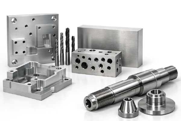
CNC machining (Computer Numerical Control machining) is a subtractive manufacturing process. CNC machining covers a number of machines that systematically remove material from a workpiece to create custom-designed components. The use of these machines began in the 1940s and 50s and has grown in market share as these machines have been refined. They offer unmatched precision and repeatability that manual machining cannot achieve.
In this blog post, we will cover the machining process, types of machines, when to use machining, and applications. If you have any questions pertaining to an upcoming project, please don’t hesitate to reach out!
Step-By-Step: The CNC Machining Workflow
CAD Design
- Software:
- AutoCAD: Excellent for 2D drafting, electrical schematics, and laser cutting or waterjet workflows.
- SolidWorks: 3D parameter modeling that is excellent for features, complex assemblies, and advanced industrial design. You’ll need CAM software, such as SolidCAM, to move from design to manufacturing.
- Autodesk Fusion: Seamlessly bridges CAD and CAM. Design the part, generate CNC toolpaths, simulate the machining process to prevent crashes, and export directly to the CNC machine.
- Preferred File Formats:
- DFX, .dxf: Drawing Exchange Format is an Autodesk format for vector sharing. Great for 2D operations such as laser cutting, plasma cutting, waterjet cutting, and routing on flat sheets of materials.
- STEP, .stp/.step: The Standard for the Exchange of Product data is great for formatting 3D CNC machining, such as milling, turning, and multi-axis machining. These files are a mathematical representation of solid and surface geometry.
- IGES .igs/.iges: Initial Graphics Exchange Specification is an older, legacy format that is excellent for surface models or basic geometric shapes.
- Design Considerations:
- DFM: Design for manufacturability makes certain features accessible to cutting tools and avoids deep pockets and thin walls.
- Tolerance Specification: Define the acceptable dimensional variation for your project’s requirements—for example, ±0.005 inches or tighter.
- Material Selection: Choose materials that are compatible with CNC (higher machinability) and that also will meet the end-use requirements.
CAM Programming
- Process:
- Import CAD files into CAM software. CAM stands for Computer-Aided Manufacturing.
- Generate toolpaths and convert the geometry into machine-readable form instructions—for example, G-code for movement and M-code for auxiliary functions.
- Simulate machining the part to optimize toolpaths and check for errors.
- Software:
- Mastercam: The industry standard for professional, complex, heavy-duty multi-axis machining. Common for aerospace and medical devices.
- Autodesk Fusion 360: Cloud-based CAD/CAM platform that is known to be accessible, affordable, and streamlined. Best for 3-axis machining with additional options for 4/5-axis machining.
- SolidCAM: A single-window integration for SolidWorks, allowing for the programming of the CNC machine with a familiar interface to the one used for modeling.
- HSMWorks: An older product. It provides integrated CAM capabilities inside the SolidWorks environment.
- Parameters:
- Feed Rate: The velocity at which a tool moves across a machine.
- Spindle Rate: The rotational speed, or how many revolutions per minute it makes.
- Depth of Cut: The amount of material removed per pass.
- Chip Removal: The plan for the formation and evacuation of metal shards to maintain surface finish and tool life.
- Coolant: Reduces the heat, helps flush the chips out, and improves the surface quality.
Machine Setup
- Fixtures and Workpiece: Make sure the workpiece is physically secure using vises, fixtures, or custom jigs for stability and repeatability. Make sure the clamps and bolts are outside the toolpath zones.
- Tool Loading: Use automated tool changers or manual loading, depending on the machine and job complexity. Perform visual checks of the tools for wear, chipping, or incorrect lengths.
- Zeroing and Work Offsets: Set Work Offsets: This refers to the machine’s reference point. Use touch probes or edge finders for the precise location.
- Calibration and Tool Offsets: Calibration Axes: Using dial indicators or laser systems for accuracy.
Material Removal Process
- Cutting Mechanics:
- Milling: Rotating tools remove the material from a stationary workpiece.
- Turning: The workpiece rotates, and a stationary tool continuously removes material.
- Parameters:
- Feed Rate: The advance speed of the tool.
- Spindle Rate: The rotational speed.
- Depth of Cut: The amount of material removed per pass.
- Chip Removal: The plan for the formation and evacuation of metal shards to maintain surface finish and tool life.
- Coolant: Reduces the heat, helps flush the chips out, and improves the surface quality.
Finishing and Inspection
- Surface Finishing:
- Deburring: This is the removal of sharp edges, rough spots, and burrs.
- Polishing: Refines the smoothness of the component’s surface by removing microscopic peaks and valleys. It gives components a mirror-like finish.
- Anodizing: A surface treatment for aluminum for additional durability and corrosion resistance. It can introduce colors or be colorless.
- Quality Control:
- CMM: Coordinate Measuring Machines are automated and offer high-precision measurements.
- Calipers, Micrometers, Gauges: Manual dimensional checks.
- Tolerances and Standards:
- Typical Tolerances: ±0.005 in or 0.13 mm. Tighter tolerances are achievable for critical components.
- Inspections: Checks against the engineering drawings and industry standards, for example, ISO and ASME.
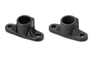
Types of Machining
| Process | How it Works | Geometries | Materials | Advantage | Limitation | Applications |
|---|---|---|---|---|---|---|
|
Milling |
The rotating workpiece and the stationary tool shape the exterior. |
3D shapes, slots, pockets, and contours. |
Metals, plastics, and composites. |
High accuracy, complex shapes, and automation. |
High setup cost and material waste. |
Aerospace housings and molds. |
|
Turning |
Rotating workpiece and stationary tool shapes the exterior. |
Cylindrical parts, threads, and tapers. |
Metals and plastics. |
Precision for round parts and efficient for volume. |
Limited to rotational symmetry. |
Shafts, bushings, and fasteners. |
|
Drilling |
Rotating drill bit creates holes. |
Holes, arrays, and patterns. |
Metals, plastics, and composites. |
Fast, accurate, hole-making. |
Limited to drilling and tool wear. |
Aerospace and electronics. |
|
Grinding |
The abrasive wheel removes small amounts for fine finishes. |
Precise flat and cylindrical surfaces. |
Hardened steels, ceramics, and superalloys. |
Tight tolerances and fine finishes. |
Slow, costly, and tool wear. |
Tooling and bearings. |
|
EDM |
Electrical discharges erode conductive materials. |
Intricate profiles, cavities, and dies. |
Conductive metals. |
No cutting force and tight tolerances. |
Only conductive materials and slow. |
Molds and turbine blades. |
|
Routing |
High-speed rotating tool cuts soft materials. |
Panels, engravings, and large parts. |
Plastics, composites, and soft metals. |
Fast, large work area, and versatile. Maintenance is limited to soft materials. |
Maintenance and limited to soft materials. |
Furniture, signs, and prototypes. |
When to use CNC Machining
CNC Machining is Ideal for:
- Material Compatibility:
- Metals: Aluminum, steel, titanium, brass, copper, tool steels, high-temperature nickel alloys, bronze, magnesium, zinc, and lead.
- Engineering Plastics: Acetal, PEEK, nylon, polycarbonate, and PTFE.
- Composites: Glass-filled nylon and Garolite (G-10).
- Part Complexity and Precision:
- Complexity: Geometries, tooling limits, and setup requirements determine the complexity of a component.
- Precision: Consistent, repeatable accuracy and fine surface finishes. These include standard tolerances, tight tolerances, and hole precision.
- Volume Consideration:
- Volume: CNC machining is cost-effective with no expensive tooling, for low-to-medium volumes and prototyping.
- Production: It bridges the gap between low-to-medium volume production and high-volume molding or casting.
- Industry Applications:
Advantages
- Superior mechanical properties and surface finishing vs 3D printing.
- Tighter tolerances and repeatability vs manual machining.
- Broad material range and rapid design iterations.
Limitations
- It is less cost-effective for high-volume production vs injection molding or casting.
- There is more material waste because it is a subtractive process than additive manufacturing.
- Set up and programming time for small production runs and one-off prototypes.
- The part’s dimensions are limited to the machine’s dimensions.
- Not suitable for complex internal geometries vs 3D printing.
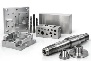
Real-World Applications: Prototek CNC Machining Services
If you’re looking to bring your designs to life with professional CNC machining, Prototek offers a comprehensive suite of CNC services.
- Processes: CNC milling, CNC turning, CNC routing, wire and sinker EDM, and 9-axis mill-turns.
- Materials: Aluminum, steel, stainless steel, brass, bronze, titanium, specialty alloys, ABS, PEEK, polycarbonate, engineering plastics, composites, and ceramics.
- Industries Served: Aerospace, defense, automotive, medical, dental, robotics, electronics, consumer, and more!
- Certifications: AS9100D, ISO 9001, ITAR, and CMMC Level 2
- Capabilities:
- End-to-end comprehensive solutions for prototyping to production.
- Over 90 materials and surface finishes.
- Assembly, welding, coating, and additional advanced finishing such as sandblasting, powder coating, anodizing, graining, electroplating, painting, and polishing.
- Quick-turn machining for rapid prototyping and fast production.
- Advanced online quoting with instant pricing, DFM feedback, and real-time lead times.
FAQs
Define: CNC Machining
CNC machining is a manufacturing technology. It uses computer-controlled machines to subtract material from a workpiece to produce a part. It allows for high precision and repeatability in the production of complex geometries.
What is a CNC machine?
A CNC (Computer Numerical Control) machine is a type of automated manufacturing equipment that uses computer programming to control the movement and operation of the machine. CNC machines can perform a variety of tasks, including cutting, milling, drilling, and shaping materials such as metal, wood, and plastic with high precision and repeatability.
What is a CNC operator?
A CNC operator is a skilled technician who operates and maintains CNC machines. CNC operators set up the machines, load the raw materials, and monitor the production process.
What is a CNC programmer?
A CNC programmer is a skilled professional who creates the instructions that control CNC machines. They analyze the engineering drawings, decide the best machining processes, and write the code that guides the CNC machine to produce the desired component.
How do you program a CNC machine?
To program a CNC machine, follow these steps:
- Create a 3D model of the part with CAD software.
- Generate the toolpath using CAM software.
- Transfer the G-code to the CNC machine.
- Set up the workpiece and tools on the machine.
- Load the G-code and run the program to produce the part.
What is a CNC milling machine?
CNC milling is a machine that uses rotational cutters to remove material from a workpiece. It can perform several operations, including drilling, boring, and shaping, to create complex parts and components with high precision and accuracy.
What is a CNC lathe machine?
A CNC lathe machine rotates a workpiece against a cutting tool to shape the material. Common uses are turning, facing, drilling, and threading several materials, including composites, metals, and plastics.
How to become a CNC machinist or programmer?
To become a CNC machinist or programmer, follow these steps:
- Obtain a high school diploma or equivalent.
- Pursue relevant technical training or an associate degree in CNC machining or a related field.
- Get hands-on experience through internships or entry-level positions.
- Learn to read and comprehend blueprints, technical drawings, and CAD/CAM software.
- Develop skills in operating and programming CNC machines.
- Obtain industry certifications, such as NIMS or FANUC, to enhance your qualifications.
- Continuously update your skills and learn to keep pace with technological advancements.