Sharp, clean edges don’t always lead to functional parts. Design features such as chamfers and fillets can impact the final product’s performance. Each of these features serves a purpose. Fillets offer smooth, stress-reducing curves, while chamfers provide crisp, angled transitions. Both features have technical, functional, and aesthetic implications. Understanding the differences helps create more functional parts.
In this blog post, we’ll explore the key differences between fillets and chamfers, their advantages and disadvantages, and provide a guide to help you make an informed decision for your next project.
Why do the edges on a part matter?
Sometimes, the most overlooked and seemingly insignificant features have the greatest impact. Edges and corners of components can influence structural integrity and manufacturability. Fillets and chamfers are two of the most common edge features—the decision between them may seem trivial. They not only affect how the part looks and feels, but also its performance.
What are the differences between fillets and chamfers?
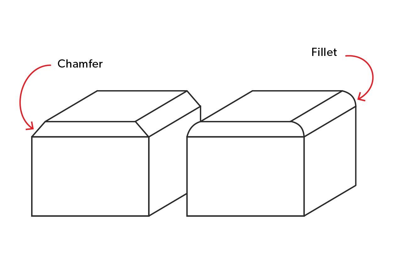
Fillets and chamfers are two standard design features used in designing components. The main difference is that a fillet is a rounded internal or external corner, while a chamfer is a beveled edge. Fillets help reduce stress concentrations and improve a part’s appearance, while chamfers facilitate assembly and improve material flow.
What is a fillet?
A fillet is a smooth, rounded curve that transitions between two intersecting surfaces, such as a corner or edge. They may be on either the interior or the exterior of a component. Fillets simplify fabrication, making machine and assembly components more accessible while promoting better flow in fluid applications. Overall, the incorporation of fillets contributes to the durability and functionality of engineered products.
What is a chamfer?
A chamfer is an angled or beveled cut at the edge of a part. Chamfers serve for both functionality and visual appeal, creating smoother transitions between two surfaces. Typically, a 45-degree angle minimizes the wear and tear of a component and reduces the chance of injury. They also reduce stress concentrations, improve the fit of assembled parts, and facilitate easier machining. Chamfers enhance the aesthetics for a more polished, professional look.
Geometric Parameters and Standard Terminology
| Feature | Definition | Primary Parameters | Typical Terminology | Industry Standard |
|---|---|---|---|---|
|
Fillet |
Rounded/curved transition between surfaces. |
Radius |
Fillet Radius and Round (External) |
ISO 582:2026 and ISO 582:1995 |
|
Chamfer |
Angled/beveled edge cut at a corner. |
Distance and Angle |
Chamfer Distance and Chamfer Angle |
ISO 582:2026 and ISO 582:1995 |
Advantages and Disadvantages of Fillets and Chamfers
When it comes to part design, including fillets and chamfers can significantly impact your components’ overall functionality and manufacturability. In this section, we’ll explore the key advantages and disadvantages of these design features to help you make informed decisions for your next project.
What are the advantages of fillets?
- Improved Stress Distribution: Eliminating sharp internal corners, fillets can prevent high-stress concentrations and increase the load-bearing capacity.
- Enhanced Aesthetics: Smooth, rounded edges created by fillets can provide a more visually appealing, professional finish to your parts.
- Easier Manufacturing: Fillets can simplify the manufacturing process, particularly in CNC machining and injection molding, by reducing the risk of tool breakage and improving part ejection.
What are the advantages of chamfers?
- Simplified Assembly: Chamfered edges act as a guide, which allows parts to mate easily and align fasteners, bolts, and shafts.
- Finishing and Deburring: Chamfers can help to remove sharp edges and burrs, reducing the risk of injury during handling and assembly.
- Safety and Handling: Chamfers protect users from cuts and injuries during handling and assembly. They also protect the part from chips and damage.
What are the disadvantages of fillets and chamfers?
- Increased Material Usage: Incorporating fillets and chamfers can slightly increase the part’s overall material requirements, potentially affecting the cost.
- Potential for Interference: Carefully design fillets and chamfers to avoid encroaching on other parts in assemblies.
- Complexity in Manufacturing: Fillets and chamfers can be time-consuming to create (with tool changes), depending on the manufacturing process and tolerances.
Industry-Specific Preferences
| Industry/Application | Fillet Preference | Chamfer Preference |
|---|---|---|
|
Stress reduction in structures. |
Panel alignment and fastener lead-ins. |
|
|
Fatigue resistance in suspension and engine parts. |
Assembly fit and deburring. |
|
|
Improved flow and reduced warping. |
Eased part ejection and assembly fit. |
|
|
High-stress parts and aesthetics. |
Cost reduction and ease of machining. |
|
|
Strength at junctions and smooth transitions. |
Print reliability and assembly fit. |
|
|
Comfort and safety in handheld items. |
Hidden/internal parts and cost-sensitive designs. |
|
|
Load distribution in beams and frames. |
How to decide which type of feature your project requires?
Here are a few questions to ask yourself when deciding whether to use a fillet vs a chamfer in your project design:
- Will your part bear heavy loads? If the answer is yes, my part will be under pressure or carry heavy loads, then you want to choose a fillet edge.
- Will parts be seen and need to be aesthetically pleasing? If the answer is yes, then the finishing needs to be visually appealing, so you may want to choose a fillet.
- Do the benefits outweigh the cost? While fillet edges are more expensive to create, they offer greater strength and structural integrity.
- Do you need to mate two components together? If the answer is yes, especially if movement is involved, chamfered edges are the best choice.
FAQs
Define: Fillet
A fillet is a smooth, rounded transition between two surfaces on a part, which improves strength and reduces stress concentrations.
Define: Chamfer
A chamfer is an angled edge or corner, used to ease transitions, improve aesthetics, and prevent sharp edges that could cause injury or damage.
How to make fillets in AutoCAD®?
To create fillets in AutoCAD®, use the FILLET command. Select the two lines or objects you want to fillet, then specify the radius.
How to make chamfers in AutoCAD®?
To create a chamfer in AutoCAD, use the CHAMFER command. Select the two lines or edges you want to chamfer, then specify the chamfer distance or angle. The chamfer will be applied to the selected edges.
Does a chamfer or fillet cost more to create in manufacturing?
A chamfer typically costs more to manufacture than a fillet.
Do chamfers need to be at a 45° angle?
Chamfers do not necessarily need to be at a 45° angle. The angle can vary depending on the specific design requirements and intended application.
Do chamfers or fillets make stronger edges?
Fillets create stronger edges than chamfers, due to their rounded shape, which distributes stress more evenly.
What is the difference between chamfers and tapers?
Chamfers are short, flat beveled edges, while tapers are a gradual, consistent change over a longer length.
What is the difference between fillets and bevels?
Fillets are rounded corners that create a smooth transition, while bevels are angled cuts that create a sloped edge that allows for better-fitting joints.
What manufacturing processes use chamfers and fillets?
Chamfers and fillets are suitable for parts made with manufacturing processes, including:
- CNC Machining
- Sheet Metal Fabrication
- Casting & Molding
- Additive Manufacturing